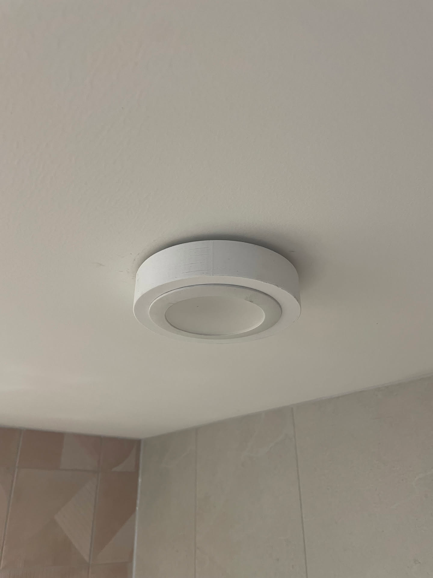

Sometimes the difficult part of fitting a downlight is not the ceiling cut-out; it is the space above it. In this project, the ceiling sat directly below a concrete slab on 16mm battens. Once the plasterboard was included, the total available recess was only about 26mm. That was not enough room for the fitting arrangement, so I designed a 30mm-deep spacer collar around the existing opening.
The model is available in the TekOnline Downlight Cavity Spacer Generator. It starts with the dimensions used in this job: an 85mm opening, 30mm depth, 25mm border and 0.8mm edge bevel.
Important safety boundary
This is a mechanical fit-up spacer, not a fire hood, thermal barrier, electrical enclosure or compliance solution. A 3D-printed part must never be assumed to create the thermal clearance required by a recessed luminaire. The exact light fitting, its driver, the printed material, nearby concrete, timber and insulation all matter.
In Australia, installation or repair of electrical equipment and cables must be performed by a licensed electrician. The electrician must confirm the luminaire manufacturer’s instructions, required clearances, ventilation and the suitability of the particular installation. Queensland’s Electrical Safety Office also specifically warns that insulation must not cover electrical fittings, especially downlights. See the Electrical Safety Office roof-space guidance and YourHome’s guidance on clearances around recessed fittings.
The shallow-cavity problem
In a typical ceiling, there is enough roof-space depth for a recessed light body, springs, driver and the manufacturer’s specified air clearance. This ceiling was different: there was a concrete slab immediately above the battens. The 16mm battens and plasterboard left approximately 26mm from the finished ceiling face to the slab.
Rather than treating the concrete slab as a cavity, the model provides a 30mm mechanical stand-off collar at the cut-out. It is intentionally simple: a hollow cylinder with a broad flat border, designed around the particular opening and spacer depth needed for the fit-up.
The default spacer dimensions
| Parameter | Default | Purpose |
|---|---|---|
| Ceiling opening | 90mm | Matches the measured cut-out used for this project. |
| Spacer depth | 30mm | Provides the required mechanical stand-off beyond the shallow ceiling recess. |
| Border | 25mm | Creates a broad collar around the opening. |
| Opening clearance | 0mm | Lets the opening be enlarged deliberately only when a test fit shows it is needed. |
| Edge bevel | 0.8mm | Softens the exposed inner and outer edges. |
| Outside diameter | 135mm | 85mm opening + two 25mm borders. |
Making the model adjustable
Every ceiling and fitting is different, so the generator exposes the five dimensions rather than locking the model to this one job. Measure the finished cut-out and the required mechanical depth, then alter the opening, spacer depth, border, clearance and edge bevel before exporting an STL.
- Opening diameter: measure the actual hole in the finished ceiling, not only the fitting’s advertised cut-out size.
- Spacer depth: set the stand-off required by the approved fitting arrangement.
- Border: ensure there is enough sound ceiling surface around the opening for the intended mechanical fit.
- Opening clearance: start at zero and add only the clearance confirmed by a physical test fit.
- Edge bevel: leave a small bevel for less sharp printed edges, or set it to zero for square edges.
Checks before a printed part is used near a downlight
- Have a licensed electrician assess the fitting and carry out the electrical installation.
- Use the specific luminaire and driver installation manual, including its clearance and insulation-contact rating.
- Do not substitute a printed ring for a tested fire-rated barrier, insulation guard or enclosure.
- Confirm the printed material will not be exposed to temperatures, UV, load or deformation beyond its documented limits.
- Check the fit with the power isolated and before the electrician completes the installation.
- Consider purpose-designed low-profile, surface-mounted or IC-rated alternatives if they better suit the fitting and ceiling construction.
Generate the spacer STL

Open the Downlight Cavity Spacer Generator, enter the dimensions for the approved mechanical arrangement, preview the ring and download the STL. The default preset recreates this 85mm / 30mm / 25mm design.
The useful lesson from this project is that a shallow ceiling can be a geometry problem worth modelling, but it remains an electrical and fire-safety decision for the fitting manufacturer and licensed electrician.