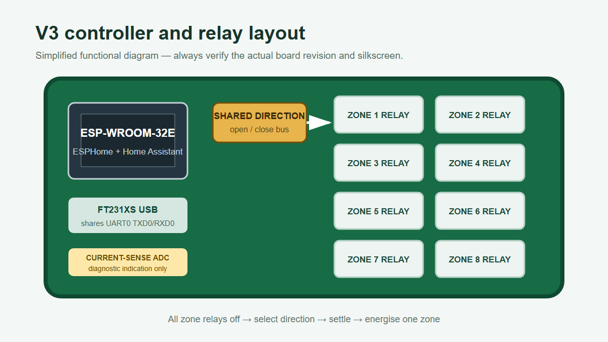
The TekOnline 8-Zone HVAC Controller V3 brings an ESPHome-first workflow to an eight-zone, 24VAC HVAC controller. Its ESP-WROOM-32E drives eight open/close damper zones and exposes each zone to Home Assistant as a cover with a familiar 0–100% position slider.
View the V3 controller or download the V3 ESPHome firmware and follow the first-board testing guide before connecting installed HVAC equipment.

What the V3 firmware controls
The V3 is an ESPHome/Home Assistant 8-zone 24VAC HVAC controller built around an ESP-WROOM-32E. It controls eight compatible open/close damper zones. The actuator motor is driven by timed relay operation rather than analogue modulation: the firmware selects a direction, enables the zone relay, and stops the motor after the requested amount of travel.

How timed 0–100% positioning works
A full open-to-close or close-to-open movement is initially configured as approximately 60 seconds. The V3 firmware uses that travel time to estimate a position. A cover command to 25% therefore runs the motor for about one quarter of the configured full-travel time.

Calibrate travel time in YAML
The starting value is set in the configuration substitutions:
substitutions:
  damper_travel_time: 60s
Measure the actual full travel of the damper you are using. If it takes 72 seconds, change the value to 72s, compile and flash again. The full calibration procedure is in the damper calibration guide.

Conservative relay sequencing in the alpha firmware
The first alpha firmware uses a conservative sequence around the shared direction relay. It turns all zone motor relays off, waits for relay contacts to settle, selects the open or close direction, waits again, and then energises one zone. A new movement stops an earlier movement so the shared direction cannot be changed while a zone relay is deliberately active.
This is a development release and must be bench-tested. Verify the raw relay mapping, direction and actuator wiring with installed HVAC equipment disconnected. The first-board testing guide explains how to do that safely.
Invert Damper Direction during setup
Damper manufacturers do not all use the same conductor order or relay polarity. The firmware exposes an Invert Damper Direction setting in Home Assistant. If an Open command physically closes the test actuator, enable the setting during setup; the cover semantics remain Open and Close while the electrical direction is reversed.

Important limitation: position is estimated
The percentage position is calculated from elapsed motor time. It is not verified by physical damper-position feedback. A power loss, manual damper movement, linkage slip, stall or missed movement can make the estimate inaccurate. Drive the actuator to a known endpoint and recalibrate when required.
The current-sense circuit can assist with electrical or damper diagnostics, such as checking whether a load signal appears while a relay is active. Current draw does not prove that the damper blade moved, reached an endpoint or is delivering the expected airflow.
Compatibility depends on wiring
The V3 is intended for compatible 24VAC three-wire power-open/power-close actuators. An RJ12/6P6C plug does not make every RJ12 damper automatically compatible. Confirm the actuator voltage, common/open/close functions, cable order, running current and stall behaviour from the actual damper documentation. Use the damper compatibility matrix as a starting point, not as a substitute for verifying the installed hardware.
Advanced UART0 development connection
The V3 exposes ESP32 UART0 TXD0/RXD0 connections for advanced integrations, including custom touch interfaces. UART0 is shared with the onboard FT231XS USB interface, so USB logging/programming and an external UART touch interface should not be used simultaneously without configuring the firmware and electrical connection appropriately. This is an advanced development feature and is not needed for normal Home Assistant use.
Firmware, setup and safety
Download the alpha YAML and documentation from the public V3 firmware repository. It includes the GPIO/relay map, secrets example, USB flash steps, raw relay test procedure, calibration notes and a Home Assistant dashboard example. Existing V2 owners can refer to the V2 controller page and the V2 ESPHome setup guide.
\n
V3 startup and bench-test correction: USB powers the ESP32 logic, but it does not power the relay coils; the board has one 24VAC input for the relay/actuator stage. Keep the damper terminals empty while checking the relay map, and apply the correctly rated, isolated and fused 24VAC supply to the board for those relay tests. On the tested revision, USB DTR is not wired to GPIO0 and SW1 is an EN reset switch, not a BOOT button, so automatic USB bootloader entry may fail. A tested manual entry held IO0 low through a 2 kOhm resistor while SW1/EN reset the ESP32; release IO0 once the uploader begins connecting. Verify the board revision and IO0 connection before following that procedure on another unit. USB-only relay tests are not a valid check. See the first-board test guide for the remaining bench sequence.
Low-voltage safety: 24VAC is extra-low voltage, but it can still cause burns, equipment damage, fire or unexpected mechanical movement. Isolate supplies before wiring, use a correctly rated fused isolated transformer, keep extra-low-voltage wiring separated from mains wiring, and follow local electrical and HVAC requirements. Use a qualified installer where required.
Ready to collaborate? Report a hardware mismatch or open an issue with the PCB revision, actuator model, measured pinout and redacted logs. Do not post passwords, API keys, customer details or production secrets.